
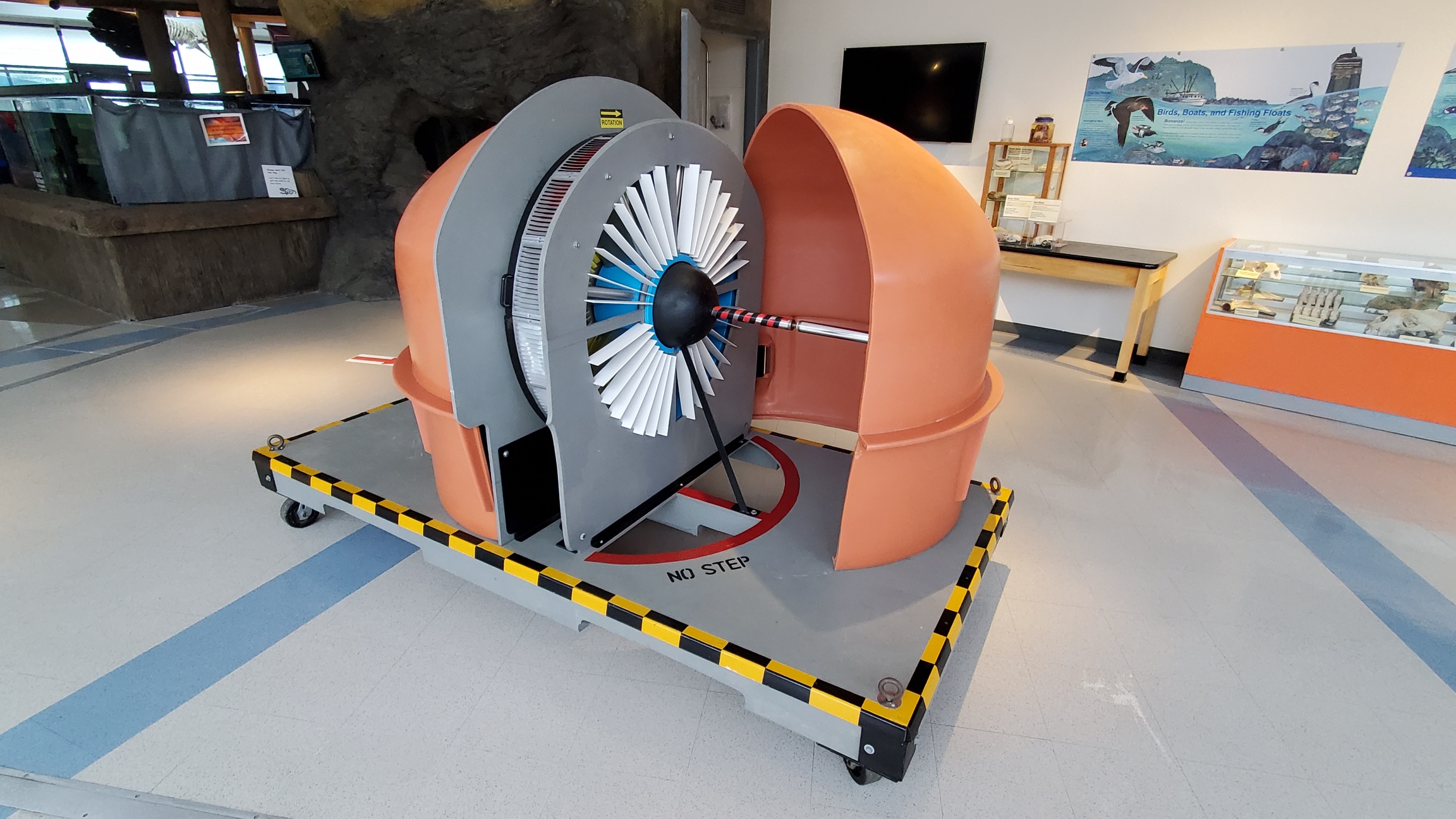
Hanna Turbine in TIDAL configuration Prototype for the original Hanna Turbine in WAVE configuration on display at Oregon State
University's Hatfield Marine Science Visitor Center in Newport, Oregon
The information below describes the Hanna Mono-radial Turbine:
PROOF-OF-CONCEPT FOR THE MONO-RADIAL TURBINE WITH AXIAL FLUX GENERATOR
In-house Proof of Concept testing was successfully completed for the mono-radial turbine by Oregon inventor John Clark Hanna. An in-depth numerical and CFD (Computational Fluid Dynamics) study for the turbine was fully-funded by the U.S. Department of Energy and was completed in March, 2022. The study validated the design as a self-rectifying OWC turbine. A full report on the study is now featured on the John Clark Hanna LinkedIn page. The new mono-radial power take-off (PTO) is a novel and exquisitely simple wave energy converter. From the exterior, the method of air intake appears to be self-evident. But inside the turbine's casement, there is a novel method of directing the air. The full force of the bi-directional air flows are efficiently harnessed to increase the rotational driving force.
Unlike common OWC (Oscillating Water Column) impulse turbines, the new Hanna PTO somewhat resembles a Pelton Wheel. The design has two iterations: 'closed loop' and 'open-ended' configurations. The closed loop design does not use valves, sensors or solenoids to help the rotor turn in one direction. Instead, the closed loop design uses two hinged 'V-shaped', self-activated guide vanes to rectify the bi-directional air flows. The closed loop configuration has balanced air flows in both directions because the flows are being pushed in on one side of the turbine and pulled out from the other side simultaneously! This improves flow efficiency inside the system. The open-ended type differs slightly from the closed loop type because its hinged 'V-shaped' guide vanes are activated by solenoids to rectify the bi-directional air flows. Both turbine iterations will use a brushless, air-cored, axial flux generator. This generator design avoids the magnetic back-torque and electrical drag that normally hinders a turbine's forward motion.
The closed-loop version is never exposed to corrosive salt water mist and the resulting marine slime that coats internal parts. The closed loop system can be miniaturized and is ideal for charging batteries on board small autonomous, extended mission research and data gathering buoys. To read the Mono-radial Turbine patent, click HERE.
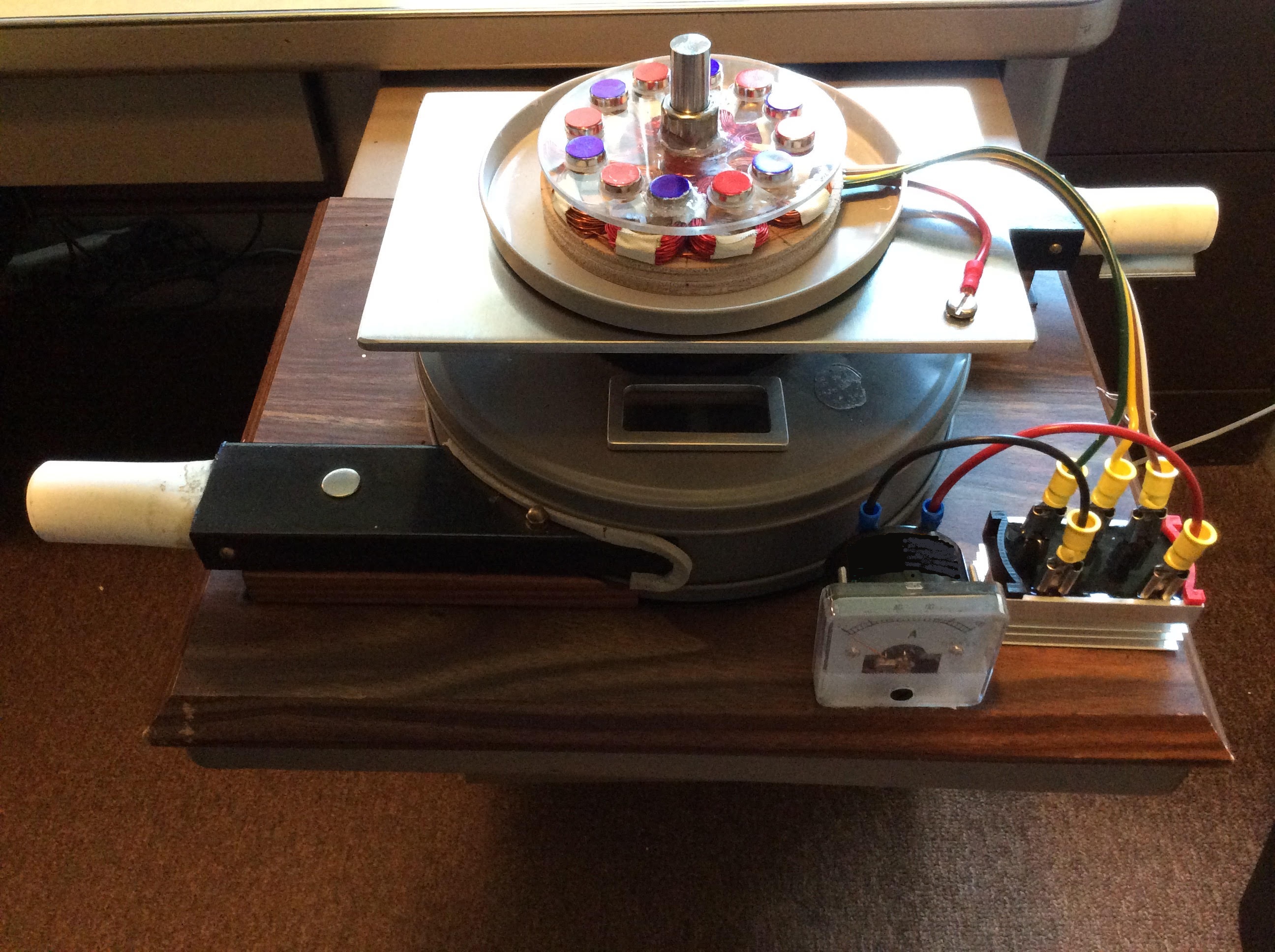
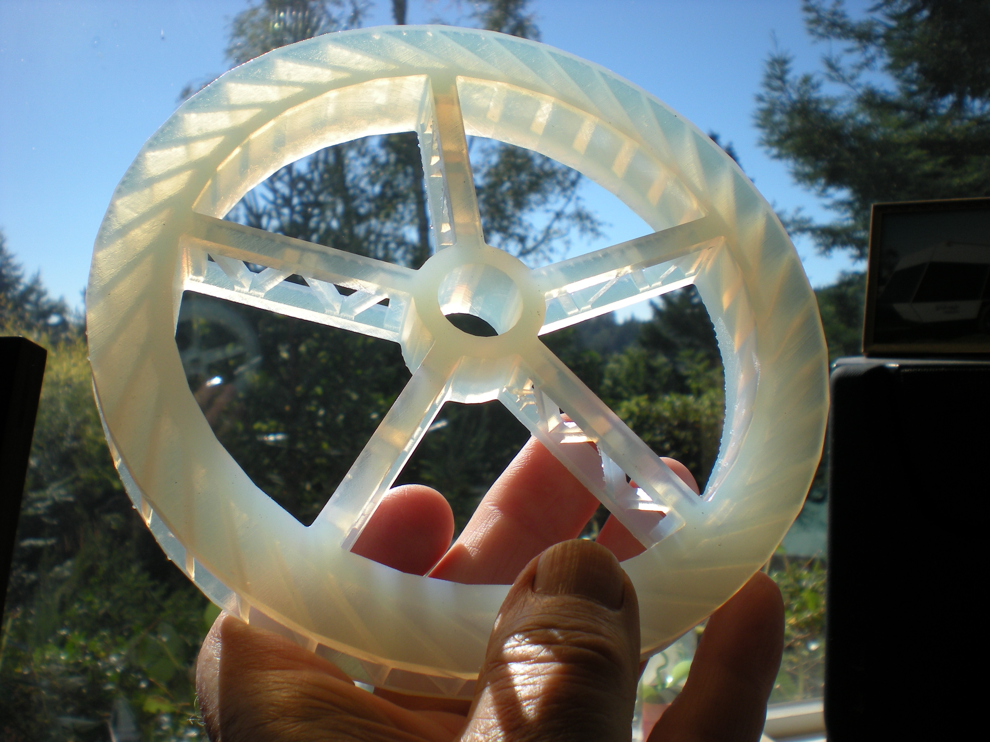
PROTOTYPE FOR THE HANNA MONO-RADIAL TURBINE IN CLOSED LOOP CONFIGURATION
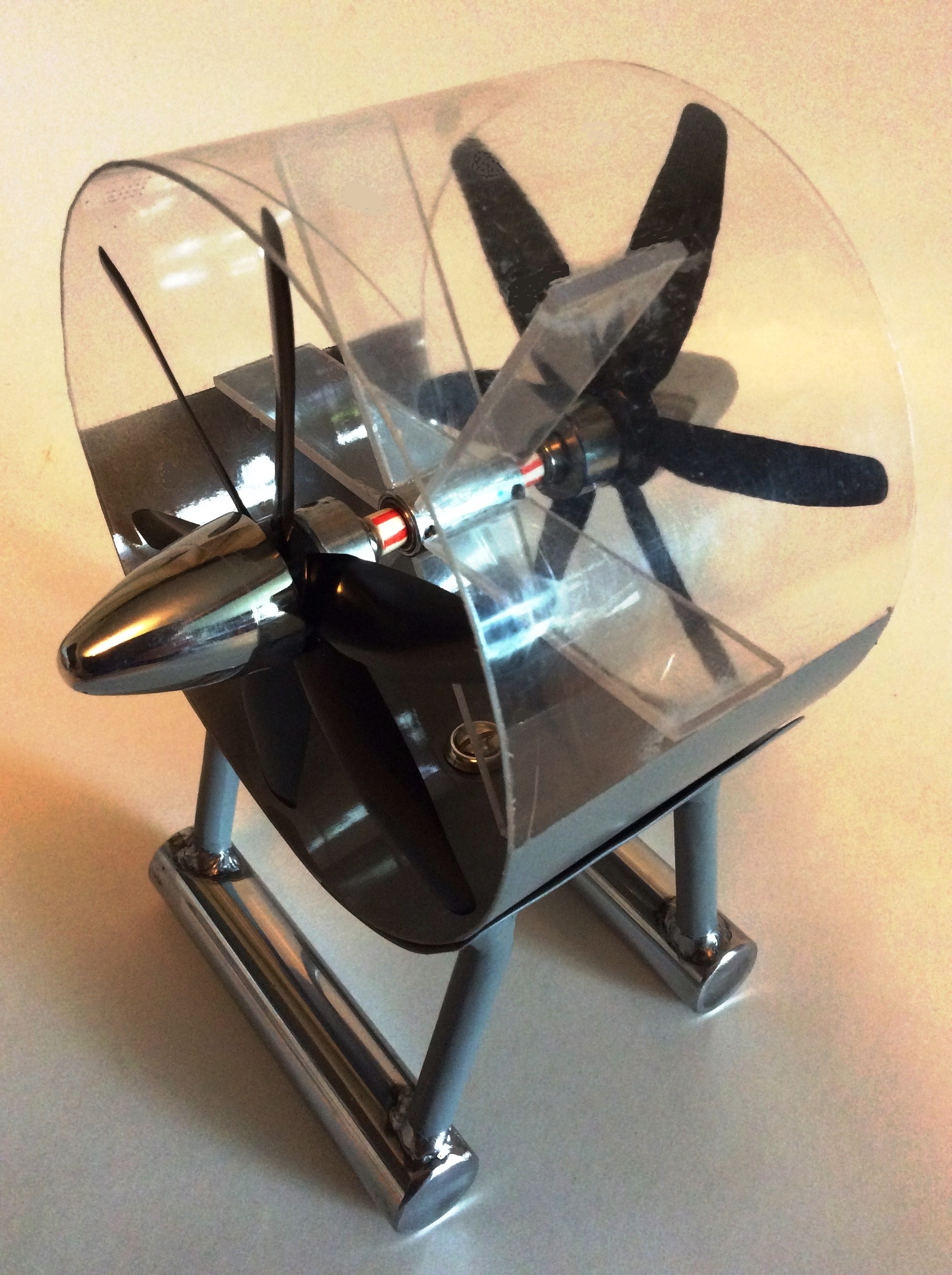
BELOW: Prototype for the Hanna Coaxial Turbine
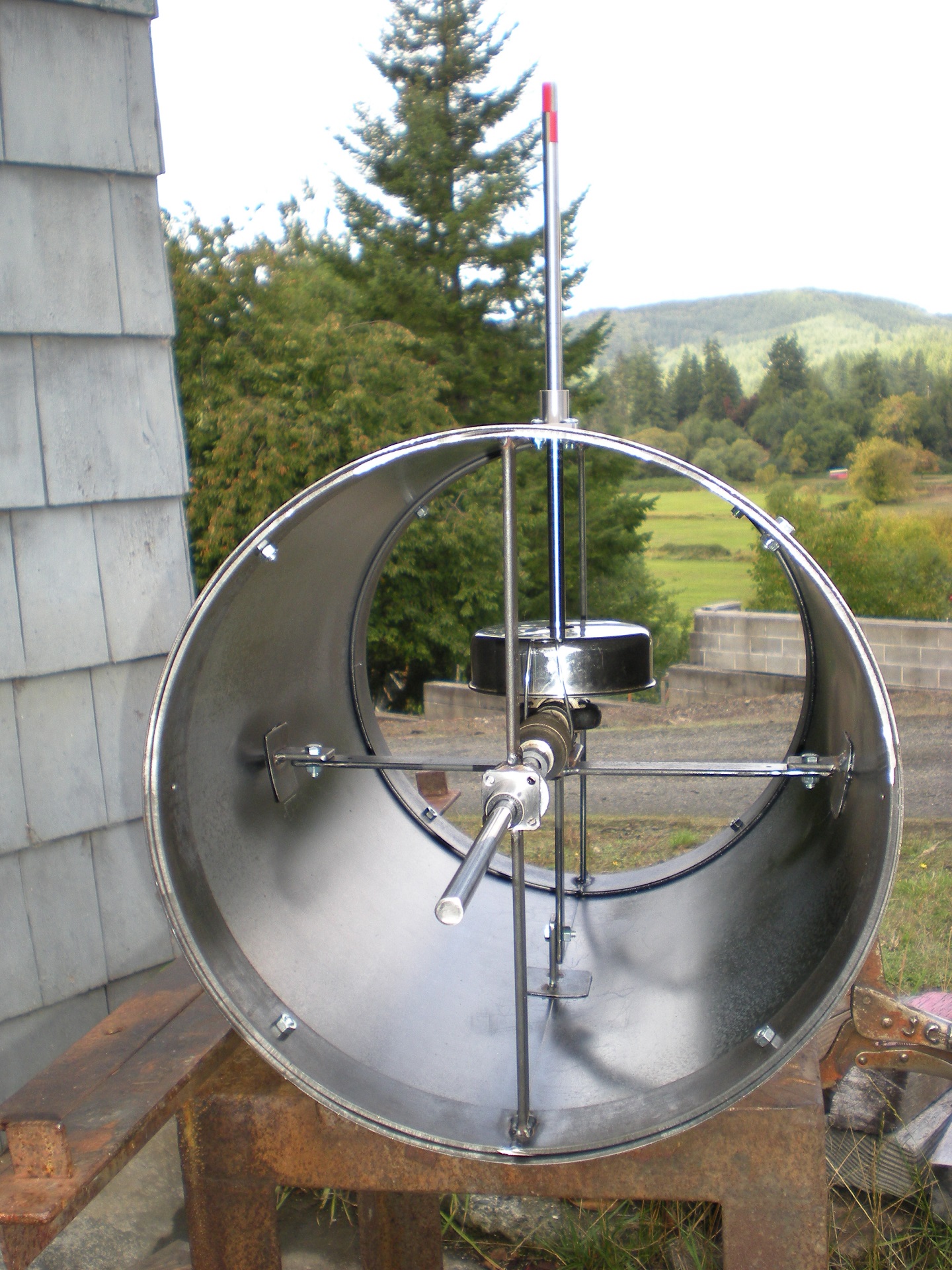
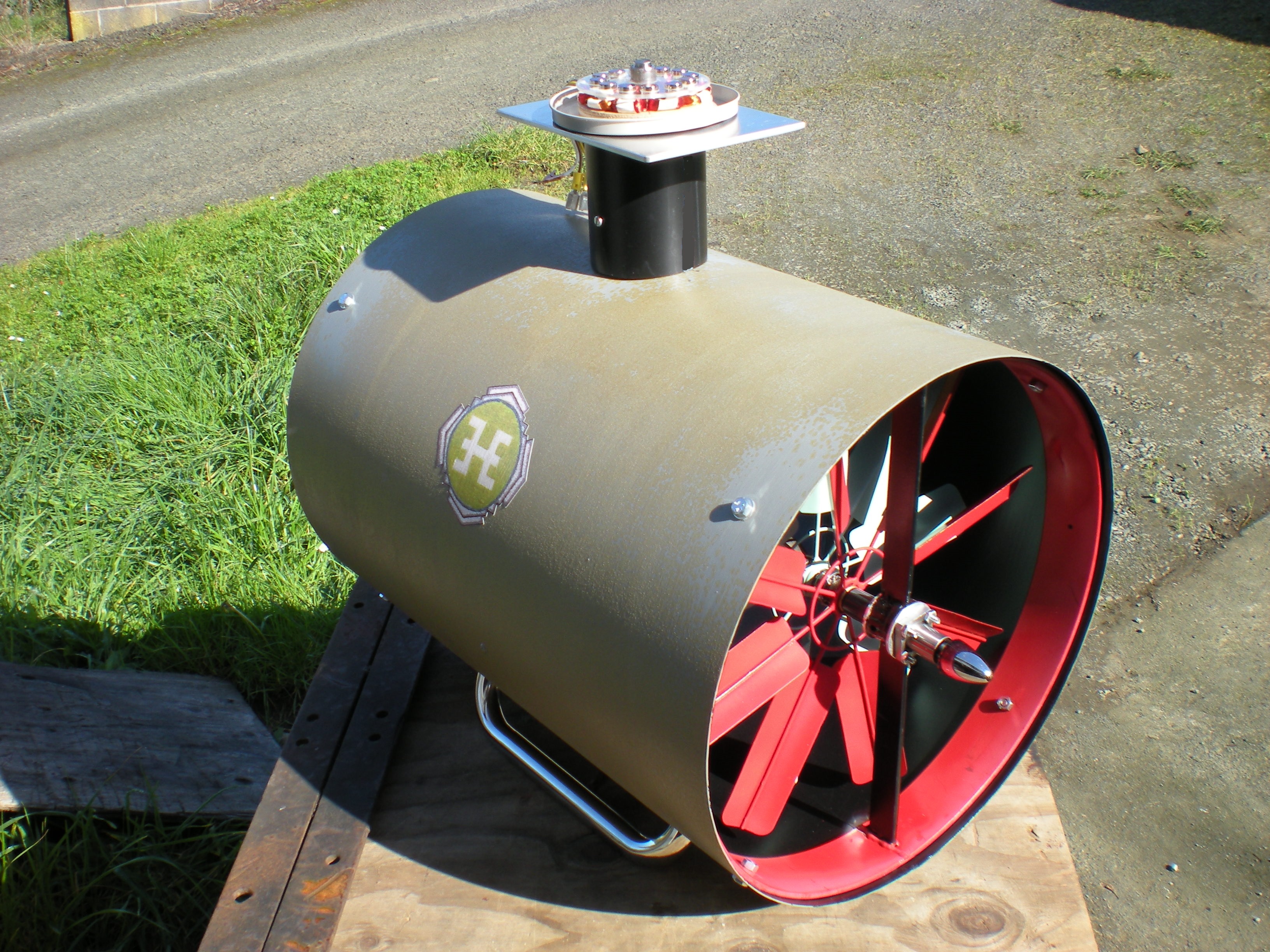
The Hanna coaxial drive will support four major marine renewable technologies: Surface and Subsurface Power Buoys; OWC air Turbines and Bi-directional Tidal Turbines. The photos above show the coaxial drive powering an OWC (Oscillating Water Column) air turbine. The same configuration, with fewer blades, will drive the Hanna bi-directional Tidal Turbine.
The air turbine uses the coaxial drivetrain and two contra-rotating blade sets to extract ocean energy. The up and down movement of waves is captured within an OWC installation which can be on a jetty or floating buoy. The turbine converts the oscillating air/water interface into a one-way rotary motion to spin a generator. Prior OWC converters have generally used a Wells Turbine to extract wave energy. Over time, however, the Wells Turbine has proven to be unreliable due to poor self-starting, stalling, and high-speed blade fatigue fracture.
The Hanna dual rotor turbine operates at slower speeds and starts easily. One-way bearings in each drive shaft allows the rotors to turn independently; one rotor drives while the other simply freewheels. Rotor drive function changes as the OWC airstreams or bi-directional tides flow back and forth. Regardless of flow direction, the upstream rotor will always be the driving rotor. Any downstream wake turbulence coming off the drive rotor will have zero influence on the downstream, freewheeling rotor's shaft due to its one-way bearing. For a full description of the Coaxial Drive, click HERE.
The coaxial drivetrain is coupled to an air core, multi-pole, axial flux generator that has no magnetic back torque and no electrical drag on the system. The generator is placed outside of the air duct, allowing unrestricted air flows to pass through the turbine for full power capture.
More Hanna Innovations: