ABSTRACT:
Described herein is a submerged utility-grade power buoy. The device is submerged below the ocean surface at approximately three meters below mean low tide. The buoy’s buoyancy chambers maintain a firm lifting force that keeps the anchor chain taught at all times to avoid any heaving motion. The buoy captures power from alternating pressure differentials generated by passing waves above the buoy and the relatively passive pressure at the buoy’s lowest point within the water column. The device is out of view from shore and is able to be anchored within the Neritic or Sublittoral Zone, i.e., relatively shallow depths from 80 feet to the edge of the continental shelf. The buoy's internal oscillating air/water interface creates an efficient pneumatic energy transfer to drive the patented PTO, a mechanical direct-drive converter known as the Hanna MultiDrive (U.S. patent 8,745,981). The subsurface buoy by itself is a generic design. The choice of PTO is what makes the buoy's design proprietary. The buoy using the patented Hanna MultiDrive PTO has been assigned to a wave energy developer in San Diego, California. However, two other Hanna-designed PTO options are still available on the submerged buoy design: a closed loop, self-rectified, Mono-radial air turbine PTO (figure four) or a self-rectified coaxial impeller drive PTO that also spins self-rectified turbines (figure three). To read more about the coaxial drive click HERE. Each of these PTO options operate in real time synchronicity within variable ranges of incident wave periods and amplitude. A wide range of power extraction is achieved when using any of the three proprietary Hanna PTO's.
OPERATING PRINCIPLE:
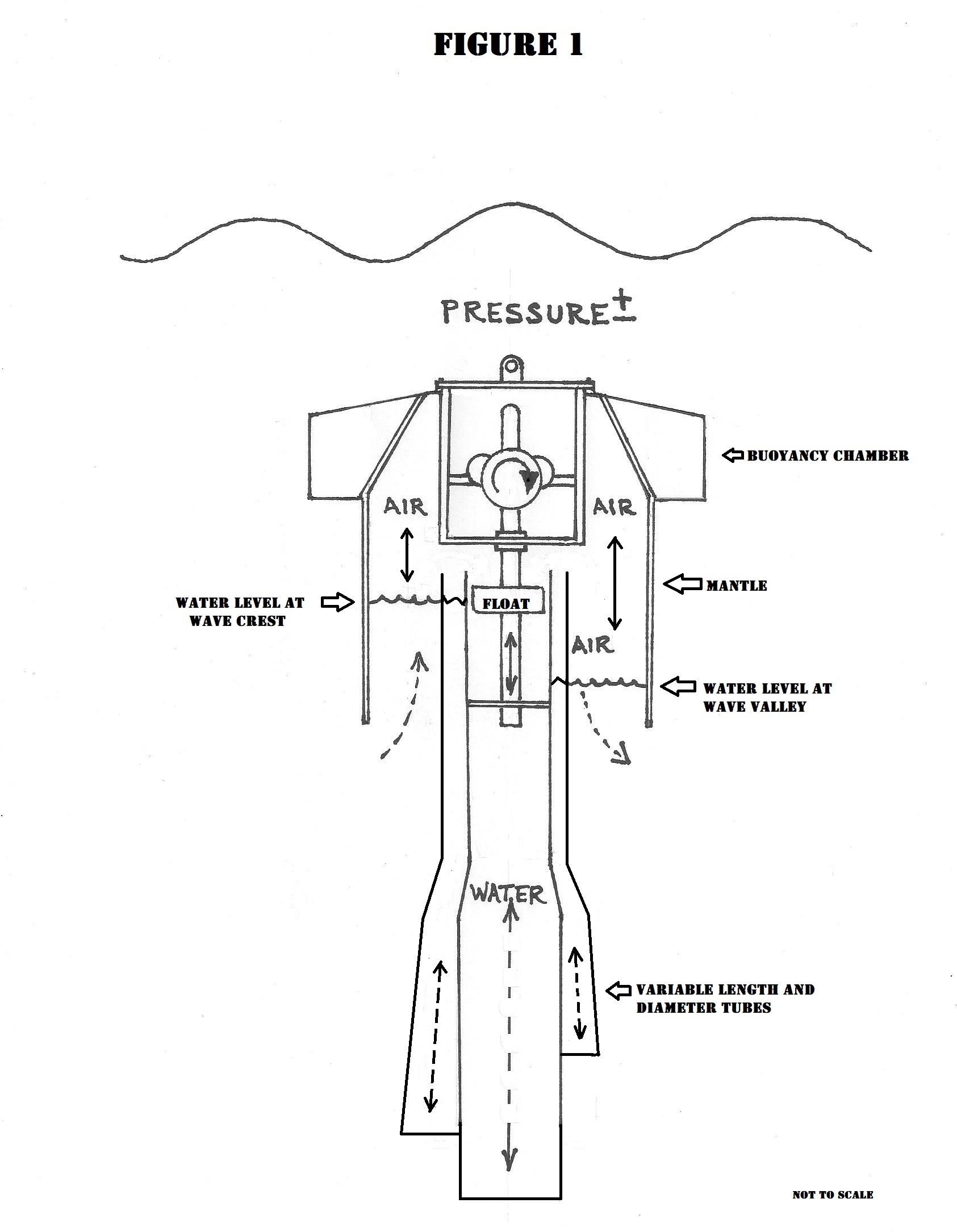
The subsurface direct-drive buoy operates on long-established principles concerning pressure gradients on a floating or submerged object as described by Archimedes. The buoy's excitation force derives from laws of fluid dynamics and pressure differentials, i.e., a volume of water is displaced within a partly air-filled container as the cyclic, differential pressures of passing waves act upon a hollow container's upper and lower extremities. As a low trough or valley between passing waves pass over the submerged buoy, the pressure decreases at the buoy's upper portion but the pressure at the buoy's lowest point is greater. The free surface of water that is contained inside the Acceleration Tube will then rise, providing a lifting force to move an internal Float upwards like a piston. The oscillating differential pressures between these two points cause a cyclic up and down movement of the free surface of the air/water interface inside the hollow buoy.
BUOY DESCRIPTION:
The buoy is a circular, hollow, structure comprised of two vertical axis components. The upper component, the Mantle, is open at its lower circumference. The second component, the Acceleration Tube, has two openings, one at its top and one at its bottom. A pocket of air is contained between both components. A precise volume of air is pumped into the Mantle when the buoy is launched. Because the submerged buoy is in a rigid vertical position, the precise volume of air remains trapped within the structure. This optimal volume of air is maintained by compressed air tanks placed in the Buoyancy Chamber. The air tanks are periodically recharged by a work vessel. When there are no waves, the free surface of water inside the Mantle and Acceleration Tube are at the same level and the pressure is equal in both components. When a passing wave crests above the buoy, the pressure differentials between the upper and lower portions of the buoy are altered and this creates a downward force that pushes out the water from the lower opening in the Acceleration Tube while, simultaneously, water is drawn into the circumferential opening at the Mantle. This causes the free surface air/water interface to rise inside the Mantle and lower inside the Acceleration Tube. When the wave crest lowers, an inverse action takes place which draws water into the Acceleration Tube and, simultaneously, forces out water at the Mantle's opening.
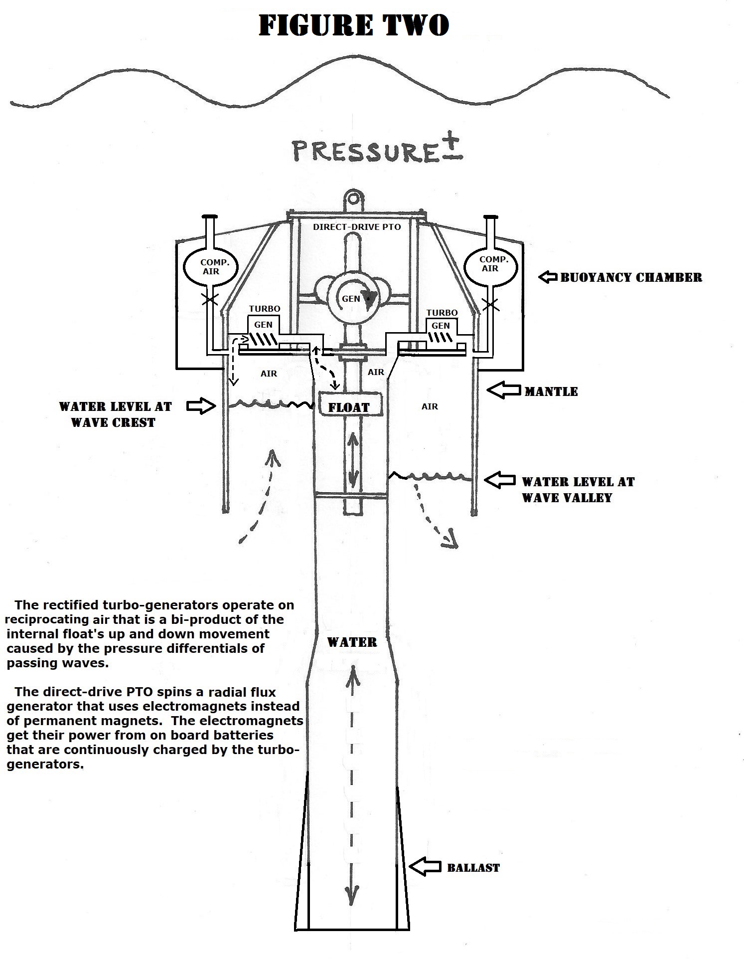
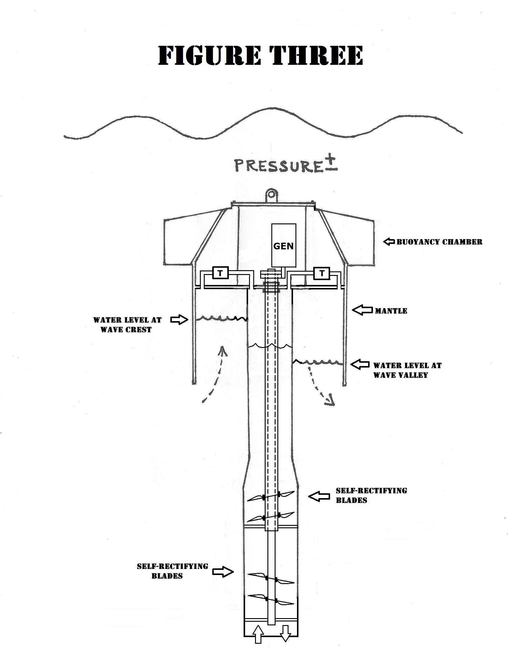
This bi-directional cycle can be harvested by three types of PTO's to spin a generator: (1), a stacked set of internal Three-blade Impellers spin within the Acceleration Tube and these self-rectified Impeller Blades rotate two coaxial shafts connected directly to a simple one-way mechanical PTO. Alternatively, an internal Float (2), will rise and fall with the free surface of water inside the Acceleration Tube. The Float is attached to a lightweight Shaft which extends upward to drive the patented Hanna mechanical direct-drive PTO called the MultiDrive. As mentioned, the MultiDrive PTO patent has been assigned. Another primary drive option (3), utilizes the rise and fall of the water inside the Acceleration Tube to create bi-directional air flows with which to spin a self-rectified, closed loop, Mono-radial air turbine (see Figure Four). The Hanna-designed closed loop Mono-radial turbine was the subject of a numerical and CFD study that was fully funded by the U.S. Department of Energy. Click HERE to read the Mono-radial Turbine patent. To read the full DOE mono-radial report, go to John Clark Hanna's LinkedIn page. Either of the three optional PTO's are sealed inside the Power Pod. The sealed Power Pod can be removed independently from the main buoy for routine maintenance operations while the buoy remains in place.
PTO DESCRIPTION:
The direct-drive PTO (FIGURES 1 and 2) mechanically converts the up and down linear action of an internal Float and Shaft into a continuous one-way rotary movement. This PTO, called the MultiDrive, spins a one-way flywheel which in turn spins generators or sea water pumps. As mentioned, the patent for this PTO has been assigned to a wave energy developer in San Diego, California. In FIGURE 2, the sketch shows a dual-drive subsurface buoy using the MultiDrive PTO as the main power generator combined with one or more small self-rectified air turbines to generate low voltage DC for the main generator's spinning electromagnets. A third patent pending design, uses two sets of stacked, self-rectifying Impeller Blades (FIGURE 3) to spin coaxial rotary Shafts which are mechanically rectified and spins a one way generator . A fourth alternative PTO is a self-rectifying turbine PTO (FIGURE 4) which is a closed loop, Mono-radial impulse-type drive. Figures 5 and 6 show the air manifold used for the turbine design shown in Figure 4. A full description of the turbine PTO can be viewed by clicking HERE.
GENERATOR DESCRIPTION
The three types of PTO drives will spin a special generator topology designed specifically for low speed and intermittent operating conditions. The generator has a torus-shape that allows for a high number of permanent magnets to be imbedded to the periphery of the spinning turbine rotor. Multiple fixed copper field coils surround the magnets that are attached to the top of the turbine's sealed casing. Both the rotor and turbine casing are composed of non-magnetic materials. The coils, have no iron cores; there is only a concentrated air-gap flux density that exists between the permanent magnets and the coil windings. This arrangement eliminates the undesirable magnetic attraction forces (drag) that is common to conventional induction-type iron-core machines. A 1-megawatt prototype for this new generator design showed up to 90% efficiency across the full operating range. Benefits are reduced weight and size and a lower LCOE.
BACKGROUND OF THE INVENTION:
The current invention is a continuation of the patent mentioned in the Abstract section above. In this new iteration, the buoy is now disposed below the ocean surface. The primary excitation force is now the pressure differentials which act upon the upper and lower extremities of the buoy.
The use of pressure differentials has been employed in various wave energy converter (WEC) designs. A prior art search for subsurface WEC's did find examples that use pressure differential excitation to drive an internal float and shaft. The earliest reference to such a subsurface power buoy is a conference paper by Markus Mueller, et al. titled: “Conventional and TFPM Generators for Direct-Drive Wave Energy Conversion” in the IEEE Transactions on Energy Conversion, Volume 20, number 2, June 2005. None of these early designs specify or claim the type of PTO as disclosed in the present invention.
Examples of prior art subsurface WEC's are: M3 Wave; CalWave Power Technologies; 40South Energy; Bombora Wave Power; a submerged buoy that uses a turbine PTO by Seung Kwan Song called SPA-OWC: US 9,518,556 B2 (now expired); another expired patent by W.W. Hirsch: US 7,199,481 B2; international patents by AWS Ocean Energy Ltd: WO2017/025765Al and US 10,711,760 B2; a patent by Marine Power Systems called WaveSub, WO20010007418A2; and patents held by Ocean Power Technologies: US 6,768,217 B2, 6,933,623 B2 and 6,768,216 B1.
An example of a prior art surface WEC is the WaveEL buoy developed by the Swedish company Waves4Power. Like the Hanna design, Waves4Power uses a float (piston) and shaft that moves up and down inside the Acceleration Tube to power their hydraulic PTO. Even when using biologic-type hydraulic fluids, the manufacturer warns: "Do not discharge into drains, soil or water". The use of hydraulic fluids could pose a threat to the marine environment.
Another surface buoy is undergoing sea trials by the Swedish company CorPower Ocean. Two CorPower PTO patent applications were filed after the Hanna patent had been granted and published. While some CorPower embodiments are similar to the Hanna MultiDrive, they are far more complex. Like the Waves4Power buoy, the CorPower PTO drives a hydraulic motor to generate electricity. Their design uses an expensive electro-mechanical phase control methodology to enhance low energy capture. Hydraulics and phase control strategies are unnecessary with the Hanna subsurface design.
A patent by Professor Lei Zuo at Virginia Tech (US 9,394,876), is for a PTO similar to the Hanna MultiDrive. His patent was issued on 7/19/2016. The Hanna patent was issued on 6/10/14. The U.S. DOE and NSF have given a great deal of support to advance Professor Zuo’s PTO design. Despite this, the Hanna PTO enjoys a distinct performance advantage over the Zuo design; the Hanna patent claims the exclusive use of free-wheeling flywheels which sustain angular momentum at the top and bottom of each stroke.
To read a comparison of the main competing designs that have similarities to the Hanna Subsurface Buoy, click HERE.
CONCLUSION:
The submerged structure is hidden from view from shore. The primary driving force is the wave-activated pressure differentials that exist between the upper and lower extremities of the submerged buoy. By integrating the patented Hanna PTO's with the proven generic subsurface buoy design, a new, greatly improved point absorber has been created. The submerged buoy enjoys many advantages over floating point absorbers: It is protected from storms and heavy seas; consequently, the buoy is less expensive to build because the structure can be much lighter than surface-type power buoys. Mooring components are lighter since there is little stress placed on its catenary-type three-point anchor system. It uses a seawater ballast system to adjust buoyancy; the ballast system is used to raise and lower the buoy for servicing. . The buoy is vertical and stable with no pitch, heave and surge motions. Being stationary, the device is not sensitive to wave direction. It does not require complex and expensive phase-control or latching mechanisms. Having no need for phase-control, the LCOE is lowered significantly. The system is versatile and can use two proprietary PTO options: When using the self-rectified Impeller Blade PTO, it continuously spins a one-way generator using 100% of the up and down wave cycle so there are no abrupt "end stops". The second PTO option is the Mono-radial, closed loop turbine which also functions without "end stops". Generators are housed within a sealed pod. The modular pod can be accessed at sea for servicing by allowing the buoy to rise to the surface. The buoy will scale from a micro grid to utility-grade sizes.
******
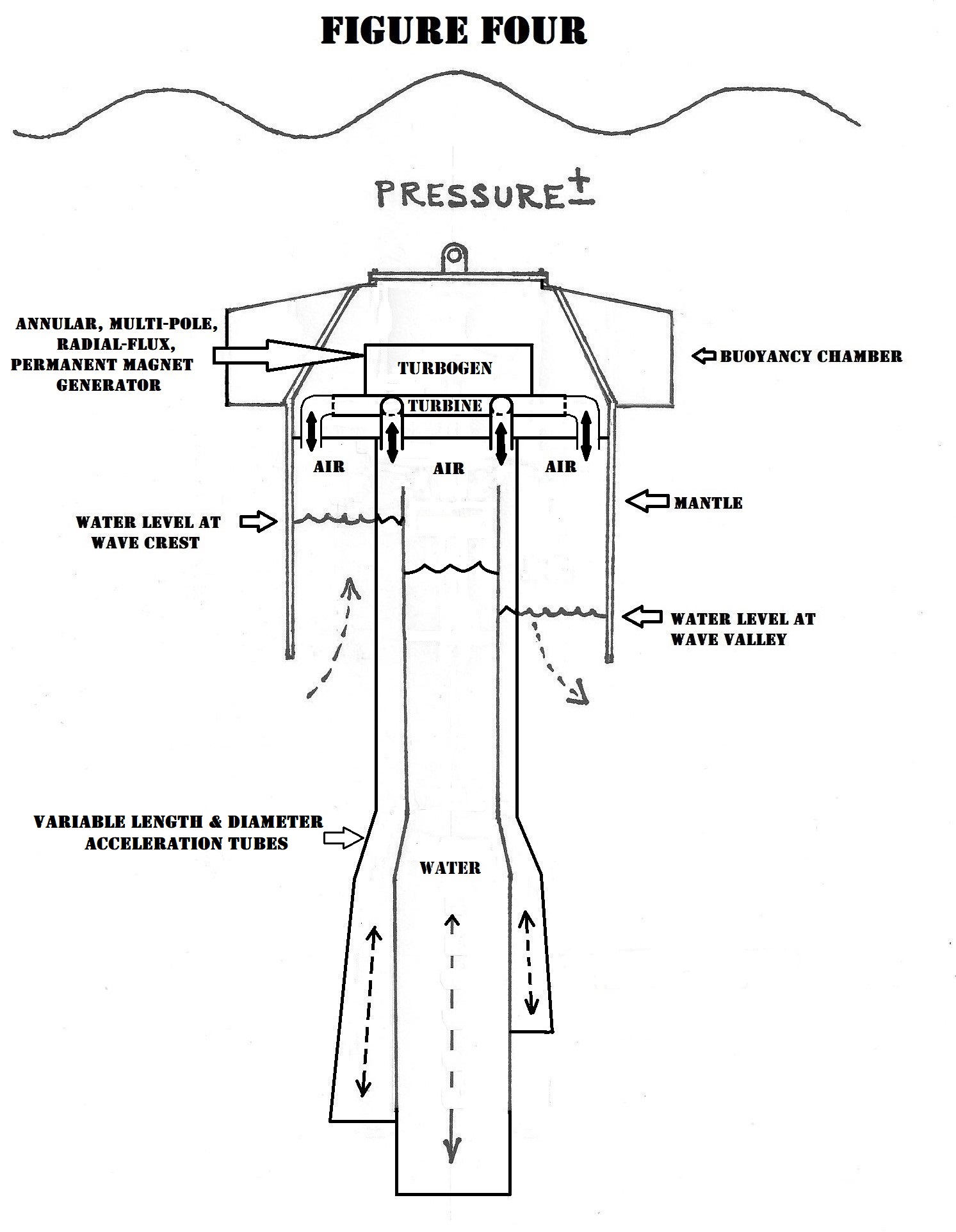
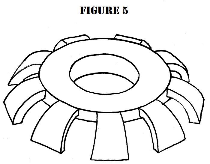
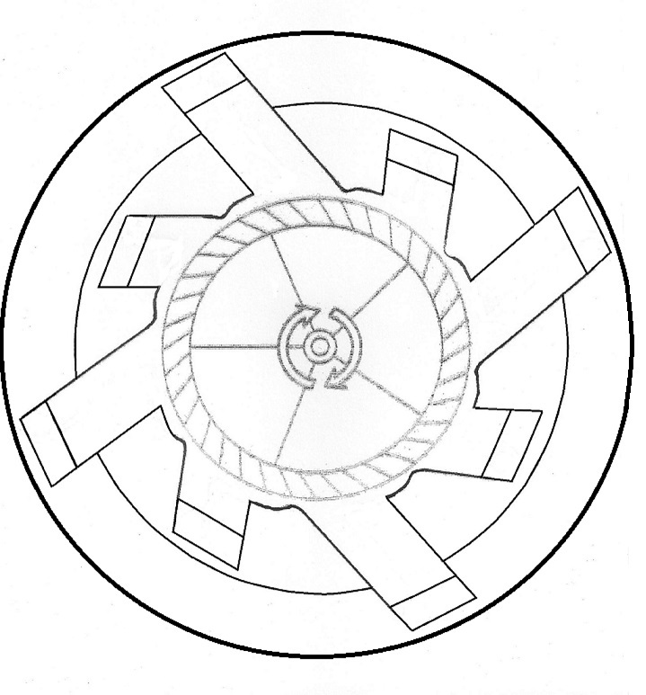
The Turbine Manifold sketch in FIGURE 5 is a general representation only. The actual manifold will have eight ducts (nozzles) as illustrated in the plan view above. Each of the eight ducts will enter the sealed rotor casement at the same angle as the rotor blade angles. The opposing ends of each duct are attached to the top of the buoy's two separate oscillating air column (OAC) compartments shown in FIGURE 4. The inner compartment is energized by the bi-directional air coming from the 'Acceleration Tube'. Trapped air inside the outer compartment called the 'Mantle', oscillates back and forth between the mantle and inner compartment. Pressure fluctuations of passing waves cause the bi-directional air flows to spin the self-rectified closed loop turbine.
About John Hanna: Interim Director of Hanna Wave and Tidal Power Drives. Navy veteran. Coast Guard documented mariner. Former skipper of the research vessel "Ed Ricketts" for California State University's Moss Landing Marine Laboratory. Mr. Hanna has twenty eight years' experience in QA/QC management on multi-million dollar government and private sector projects for structural steel and welding. He was contracted by Ocean Power Technologies as the QC manager for their PB-150 PowerBuoy built in Oregon. Hanna Wave and Tidal Power Drives is registered with Dun & Bradstreet.
Return to HOME PAGE