Both technologies described below were initially meant to become U.S. Utility Patents. But the patent process is ponderous and time consuming and time is running out. Climate Change is now at a tipping point. It may already be too late to reverse the pending catastrophe. So, I have decided to offer both of my inventions as 'open-source' technologies. With the appropriate citation, they are freely available to developers around the world. The coaxial drivetrain is new for wave and tidal energy, but the converters that are driven by my new coaxial system are common, proven technologies. The second open-source technology being offered, is my Monoradial Drive. It has been validated by a DOE-funded study using computational fluid dynamic analysis. Both PTO systems have the potential to reward anyone who invests time and resources to bring these ideas into the global market. It is my hope that these concepts will be adopted by others who feel as I do. We have to act now in order to protect Earth's ability to sustain life. I will consult with any developer to help make this happen.
Inventor: John Clark Hanna
Provisional Patent: 63/420,846 (abandoned)
Contact: wetgen@gmail.com
Title of the Invention
Coaxial PTO Drives for Wave, Tidal and OWC Air Turbines
ABSTRACT
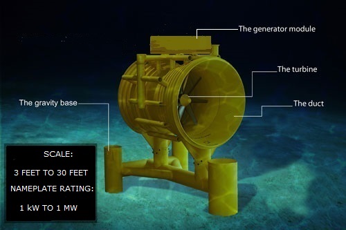
A novel coaxial drivetrain called the “Tidal-Wave Drive,” that supports five major Wave Energy Converter (WEC) systems: (1) platform and shore-based installations; (2) surface floating buoys; (3) submerged buoys; (4) bi-directional tidal converters; and (5) OWC self-rectified air turbines. In each application, the coaxial power take-off (PTO) mechanically rectifies bi-directional fluidic flows to spin a one-way generator. The mechanical drive system has two or more sets of impeller blades which are energized by the alternating movement of waves or tides.
Coaxial drivetrains have been used in dual rotor helicopters for decades. A global patent search shows there are NO existing self-rectifying coaxial drivetrains for wave and tidal applications!
SURFACE BUOY, or OWC AIR TURBINE OPERATION
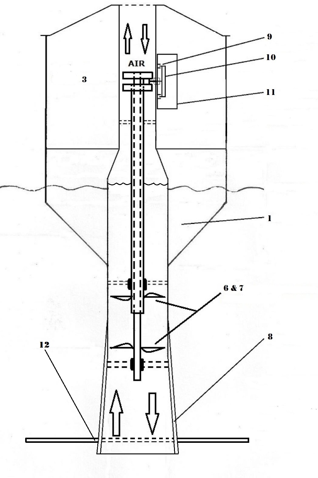
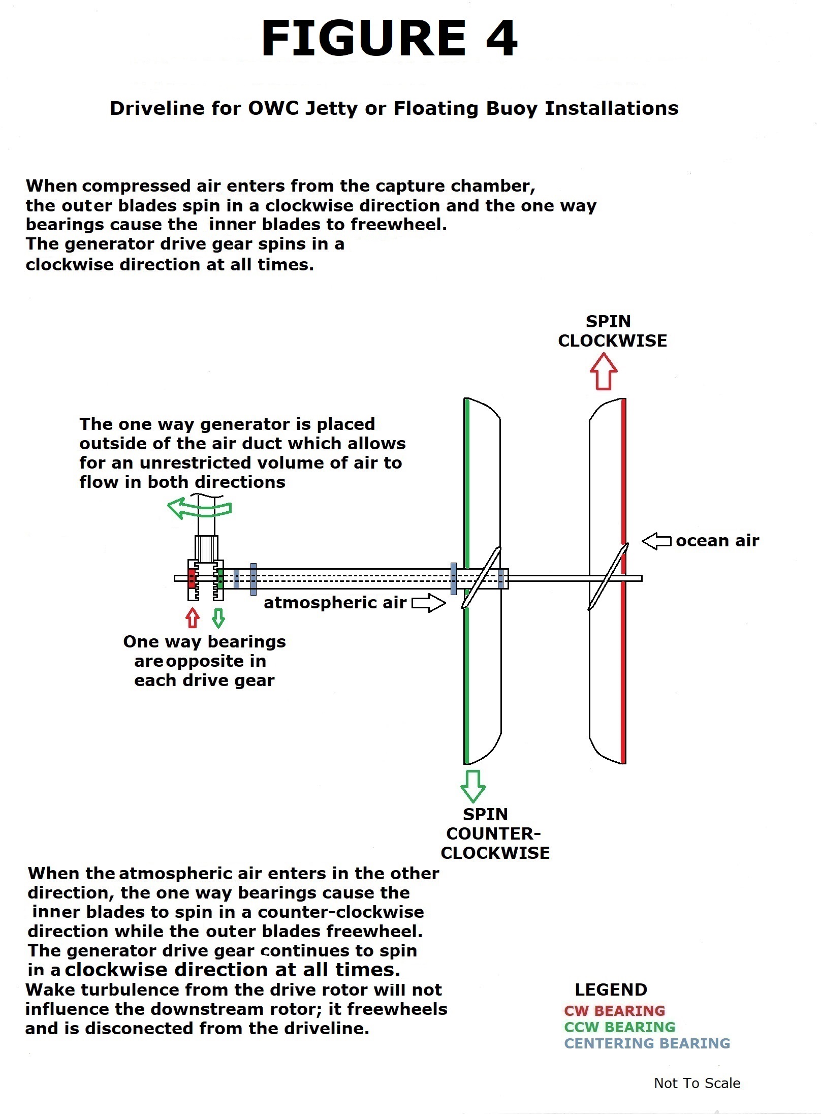
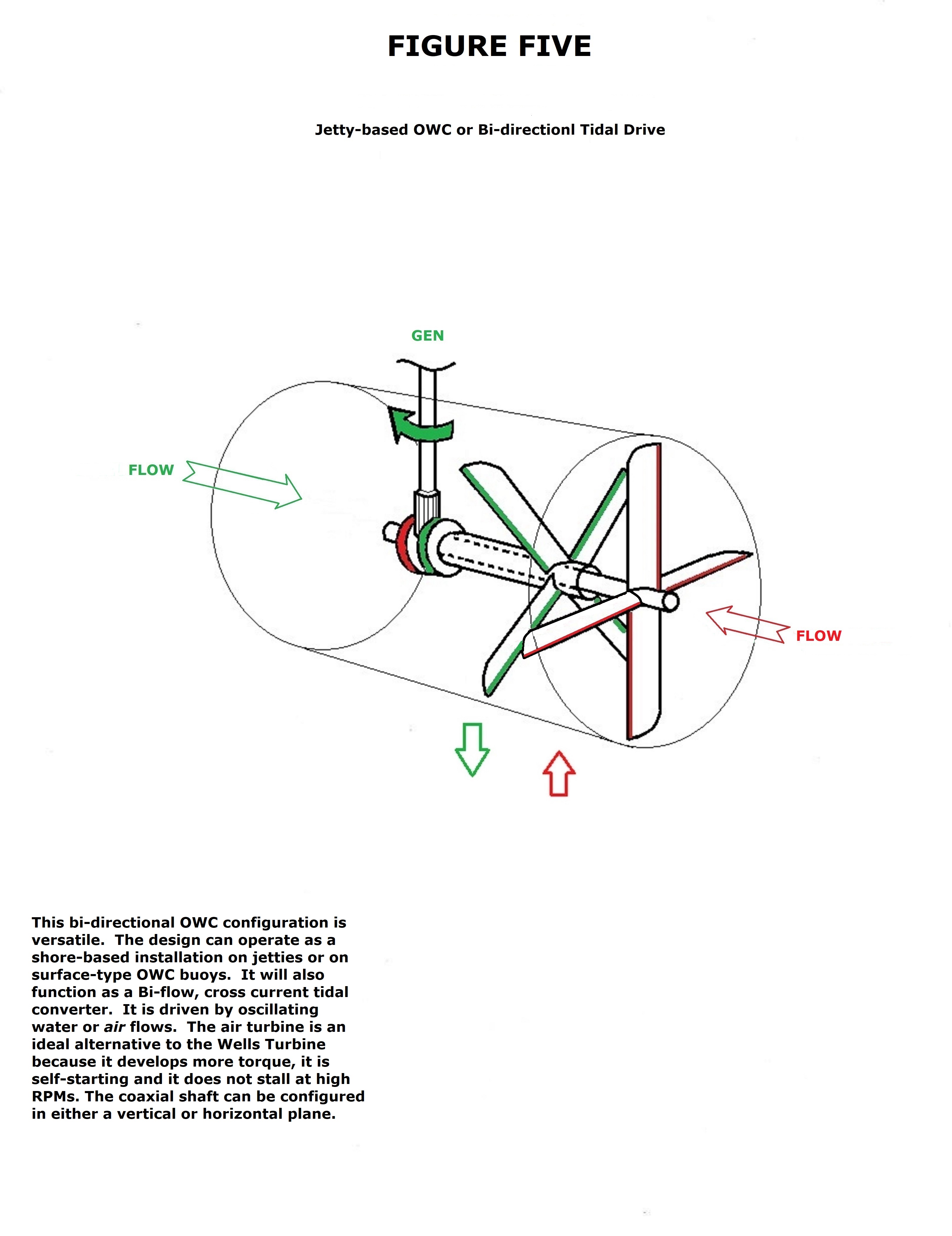
The Surface Buoy iteration (Figure Two) shows how the generator drive shaft is offset at a ninety-degree angle from the primary coaxial drive line. The reason for this 90-degree bend is to allow the oscillating air column to pass in and out freely through the top of the floating buoy. The 90-degree bend also allows unrestricted bi-directional flows in the jetty-based, floating platform-based, tidal, and rectified air turbine iterations. The 90-degree iterations have the coaxial drive shafts and blade sets orientated so they will counter rotate from one another. Figures 3 and 4 provide details of the drivelines for both types of buoys – subsurface and surface. The driveline in Figure 4 can also be applied to bi-directional tidal, surface buoy and jetty-based or rigid floating platform-based converters. The tidal and air turbine iterations shown in Figure 5, have the impeller blades and coaxial drive shafts surrounded by a circular enclosure or nacelle which is open at both ends, thus allowing the unrestricted bi-directional flows to pass through freely. View a video that explains how the turbine works: https://youtu.be/wdN50FahwXw .
TIDAL TURBINE OPERATION
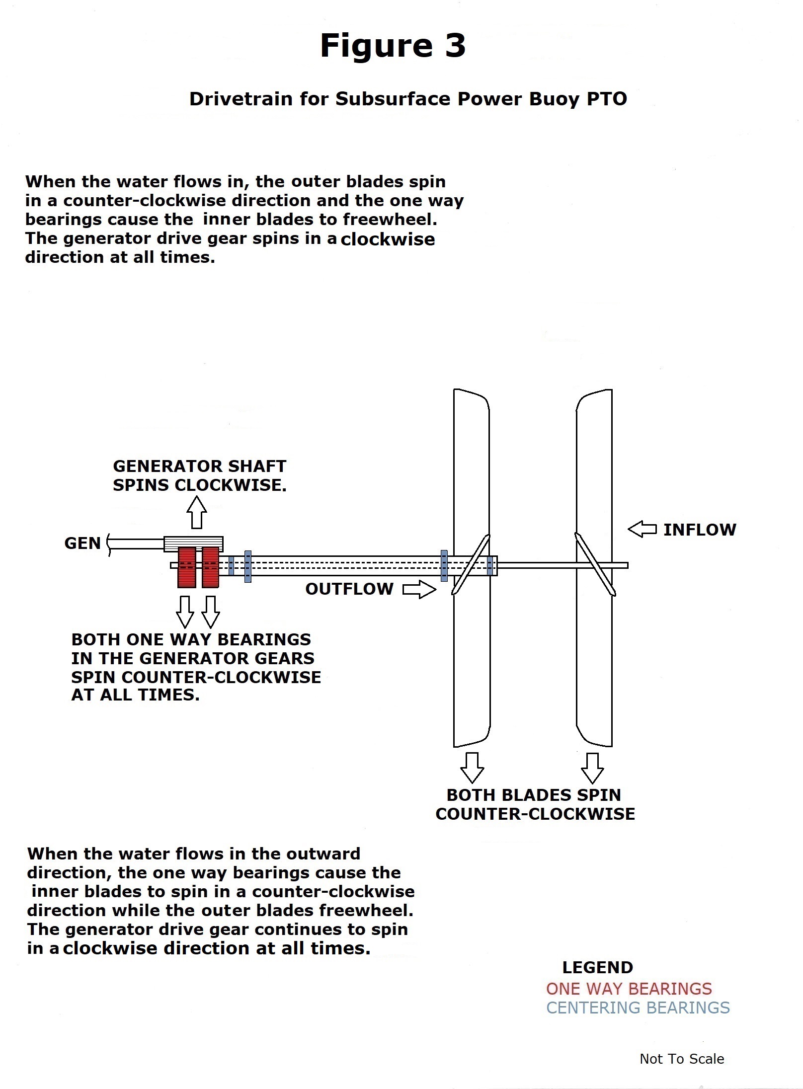
The tidal energy device (Figure 5) mechanically self-rectifies bi-directional flows into a one-way rotary motion to spin a generator. This is accomplished by utilizing a contra-rotating, dual rotor coaxial drivetrain. One-way bearings in either driveshaft allows each rotor to spin independently from the other. Depending on tidal direction, the upstream rotor will engage its respective drive shaft whilst the other downstream rotor simply freewheels. This arrangement eliminates the need for expensive passive or active pitch controls on the rotor blades. The tidal device remains fixed; effortlessly harvesting estuarine or river outlet flows without swinging on its mooring or yawing on a pylon. The design is adaptable; it can be used as an OWC air turbine or as a tidal turbine. The 90-degree bend in the driveline places the generator in a dry module outside of the duct. This arrangement allows an unrestricted flow path through the turbine. It is important to stress that any wake turbulence coming off the upstream (driving) rotor will NOT influence or have a negative effect on the downstream (freewheeling) rotor; the downstream rotor is always disconnected from the drivetrain! View a video showing a working tidal turbine prototype and see how it rectifies the bi-directional water flows into a one-way rotary motion to spin a generator: https://youtu.be/UXYR4ETw6_Up .
SUBSURFACE BUOY
In the submerged buoy, the device is a rigid two-body structure where the impeller blades are attached to a coaxial drive line positioned inside an Acceleration Tube (see Figure One). The submerged-type of buoy is a proven design that exists in the public domain. What is new is how the subsurface buoy platform uses two types of PTOs to harvest the internal bi-directional flows: the first PTO employs the impeller-driven coaxial drive to mechanically spin a main generator. The second PTO is a closed loop pneumatic system that drives one or more auxiliary turbogenerators. The auxiliary turbogenerators provide power for the main generator’s electromagnetic field coils, which eliminates the need for expensive rare-earth permanent magnets in the main generator.
Subsurface Operation
When there are no waves, the free surface level of water inside the Mantle and Acceleration Tube are at the same level. When a passing wave crests above the buoy, the pressure differentials between the upper and lower portions of the buoy are altered and this creates a downward force that pushes out the water from the lower opening in the Acceleration Tube while, simultaneously, water is drawn into the Mantle opening. This causes the free surface air/water interface to rise inside the Mantle and lower inside the Acceleration Tube. When the wave crest lowers, an inverse action takes place which draws water into the Acceleration Tube and is pushed out at the Mantle opening. This perpetual reciprocating cycle allows the free surface of water to rise and fall within the Acceleration Tube. The reciprocating water flows will energize the coaxial drive PTO. Simultaneously, the fluctuating air/water interface acts like a piston; forcing air through the turbogenerator(s) and passing the air on to the Mantle’s air containment cavity. The reciprocating air drives the auxiliary self-rectified turbine PTO in a closed-loop system. The reciprocating water spins the self-rectified impeller PTO.
Subsurface Buoy Mechanical PTO
The subsurface buoy’s mechanical drive is an impeller system. Two or more stacked sets of flat, symmetrical rotor blades are attached to coaxial drive shafts. One-way bearings in each shaft allows them to engage in one direction only as the water flows pass back and forth across the impeller blades. Water is 784 times denser than air so the mechanical PTO will develop high torque values to drive the main generator.
The buoy is submerged below the ocean surface and attached to the sea floor (see Figure One). The device is out of view from shore and can operate within the Littoral Zone at relatively shallow depths from 80 to 150 feet. The device is a hollow, two body structure consisting of a Mantle and an Acceleration Tube. Both structures are rigidly attached to each other and the entire assembly is held in a fixed semi-vertical position by a three-point catenary anchoring system.
Compressed air tanks and sensors maintain a precise volume of air between the Mantle and Acceleration Tube. The compressed air tanks are periodically re-charged by a work vessel. The design allows a direct, highly efficient, one-to-one energy transfer to the PTO. The direct-drive PTO generates power in real time synchronicity within the variable ranges of oceanic wave periods and amplitude. Being able to operate below the surface eliminates the need for complex reactive phase controls or latching methods designed to match resonant wave frequencies and to compensate for reflecting wave losses common to all surface point absorber buoys. The submerged buoy has a higher likelihood of survival in extreme sea states. A continuous wave-activated bi-directional flow of water fluctuates inside the Acceleration Tube of the OWC buoy. Both PTO systems are energized by these flows. The subsurface buoy’s mechanically-driven PTO is made up of two pipe shafts with one drive shaft centered inside the other. Centering bearings are distributed between the shafts, allowing each drive line to rotate freely from the other.
At the low end of the Acceleration Tube, the inner drive pipe extends beyond the outer drive pipe. The extended inner pipe has two stacked sets of impeller blades attached. The other outer pipe also has two stacked sets of impeller blades and these blades are mirror-images of the other set.
In order create a mechanical one-way drive that will spin a generator in one direction only, the PTO design calls for two sprag-type, one-way, clutch bearings to be attached to the upper ends of both drive shafts; one bearing located on top of the other. The inner races of the two clutch bearings are fixed to their respective shafts and the outer races are keyed inside two stacked drive gears that have identical outside diameters. Thus, when one shaft rotates in one direction, the other shaft will simply freewheel. The active shaft’s driving gear will engage the generator pinion gear to spin it in one direction only while simultaneously, the other driving gear will freewheel. Then, when the water flow reverses, the drive modality also shifts; the former drive shaft will now freewheel whilst the second drive shaft engages and will now drive the generator.
Therefore, when water flows in one direction inside the Acceleration Tube and the upstream (driving) set of blades are activated by the passing water, the downstream set of blades will rotate independently and freewheel. It is also important to note that regardless of how turbulent the downstream water might become as it comes off the driving blades, the disengaged downstream blades will be unaffected by any turbulence or cavitation. The downstream flows coming off the drive blades might cause the downstream blades to spin in the reverse direction or slowly spin in the driving direction or simply stay stationary. The disengaged downstream blades are unaffected by the engaged upstream drive blades. The upstream blades are the dominate blades that capture the bi-directional flows.
Subsurface Buoy Pneumatic PTO
The subsurface buoy employs a second way to harvest wave energy to energize one or more self-rectified air turbine PTOs. Waves cause water to rise and fall within the Accelerator Tube. The free surface of water at the air/water interface acts like a piston. As the water level rises inside the Accelerator Tube, the trapped air is compressed and is forced through one or more auxiliary turbo-generators installed inside a water-tight compartment. After passing through the turbines, the air travels into the buoy’s Mantle (see Figure One). As incident waves pass above the submerged buoy, the pressure differentials created by the waves cause the buoy’s entrapped air to pass back and forth from the Mantle to the Acceleration Tube in a continuous cycle. This bi-directional air flow is channeled through the auxiliary self-rectified turbines and generates electricity. The turbines can be optional impulse-type, Wells reaction-type, or the Hanna-designed impulse/reaction-type [2]. The air turbine(s) drive generators that can produce power for the grid or, alternatively, develop low voltage DC power for charging on-board batteries to power electronic payloads and/or provide power for the main generator’s electro-magnetic field windings. This arrangement eliminates the need for costly rare earth permanent magnets in the main generator.
PRIOR ART BACKGROUND OF THE INVENTION
Examples of prior art subsurface WEC's are: M3 Wave; CalWave Power Technologies; 40South Energy; Bombora Wave Power; a submerged buoy that uses a Wells Turbine PTO by Seung Kwan Song [1] called SPA-OWC: US 9,518,556 B2 (patent now expired); another expired patent by W.W. Hirsch: US 7,199,481 B2; international patents by AWS Ocean Energy Ltd: WO2017/025765Al and US 10,711,760 B2; the Dutch company Symphony Wave Power has a submerged buoy that shares its operational cues from the AWS buoy; a patent by Marine Power Systems called WaveSub, WO20010007418A2; and patents held by Ocean Power Technologies: US 6,768,217 B2, 6,933,623 B2 and 6,768,216 B1.
Examples of a prior art surface WEC’s that use direct-drive PTOs are the WaveEL buoy developed by the Swedish company Waves4Power; a dual rotor WEC by the U.K. company Inyanga Tech [2] US 8,358,026; and a dual PTO WEC by Ocean Motion Technologies [3] US 8,745,981.
BRIEF DESCRIPTION OF THE FIGURES
The subsurface iteration (Figure One) requires that both sets of impeller blades rotate in the same direction. This mechanical PTO turns a top-mounted one-way drive gear which spins the buoy’s main generator. The rising and falling air/water interface within the Acceleration Tube drives one or more air turbines to spin secondary generators. The secondary generators can either add power to the main generator’s output or they can generate low voltage DC power for payload electronics and/or for the main generator’s electromagnetic field windings.
Nomenclature for the two figures
G) Main Generator
C) Compressed Air Tanks and Valves
T) Auxiliary Turbogenerators
References
[1] Subsurface Buoy wave tank demo: https://youtu.be/Z2chGWLS1IA
[2] A wave or tidal PTO with a single axle, in-line generator and dual rotors, US 8,358,026
[3] A dual PTO surface buoy with a float-activated linear to rotary drive, US 8,745,981
It is claimed:
(b) A secondary energy conversion system is employed in the submerged buoy as described in claim 2 where air is contained within the buoy and the oscillating air/water interface acts like a piston which forces the entrapped air to pass back and forth within a ducted closed loop system through one or more auxiliary self-rectified turbogenerator(s) placed within the submerged buoy.
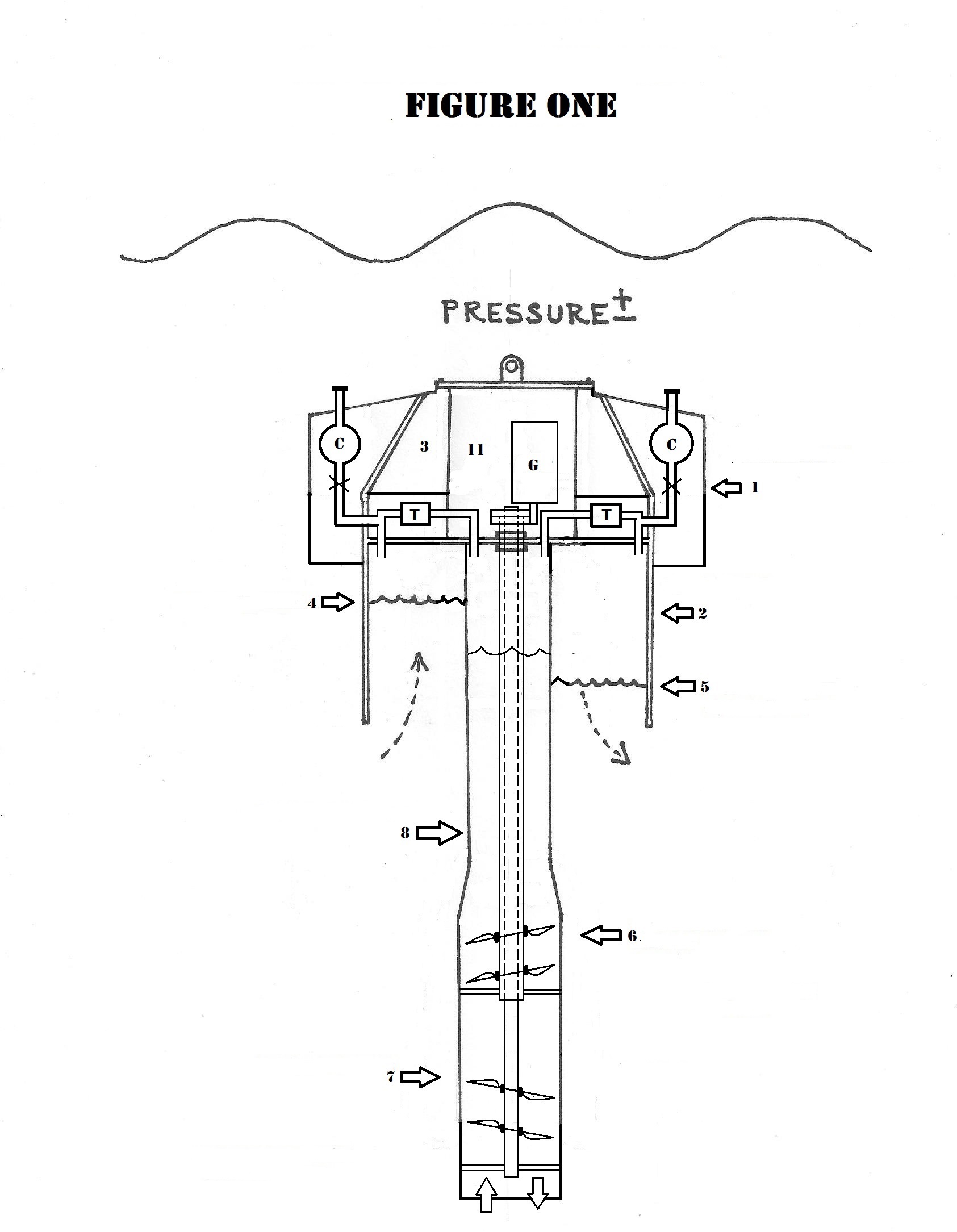
Figure Two
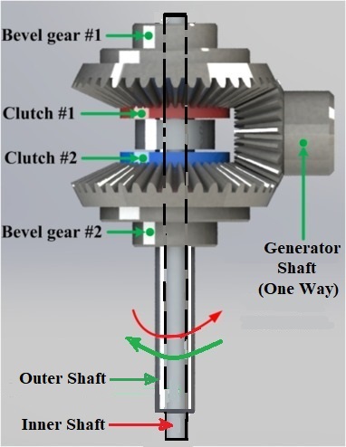
Above: The Contra-Rotating Coaxial Drive in Figures 2, 4 and 5
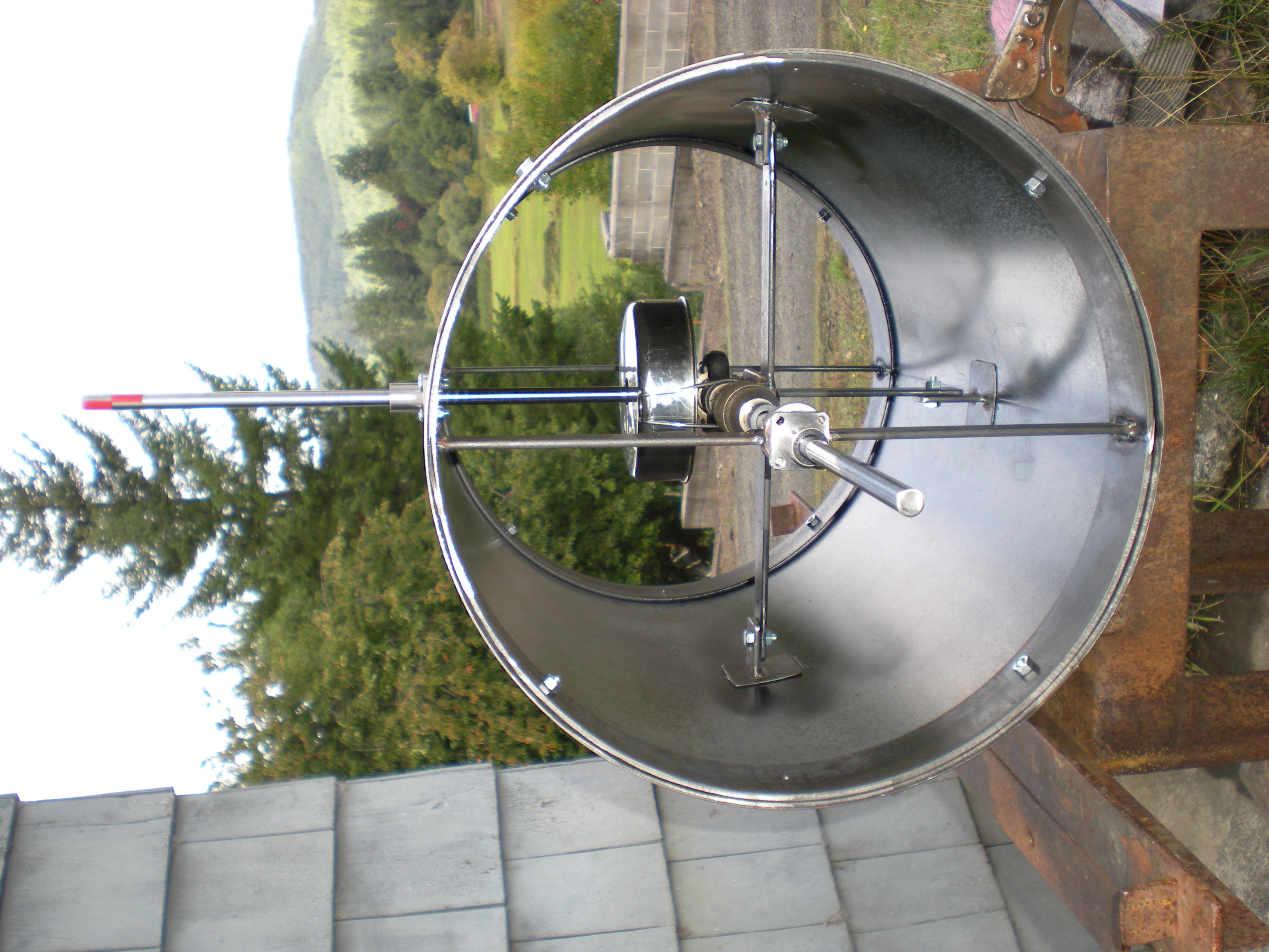
Prototype/proof-of-concept for the contra-rotating coaxial drive as illustrated in Figures 2, 4 and 5 above.
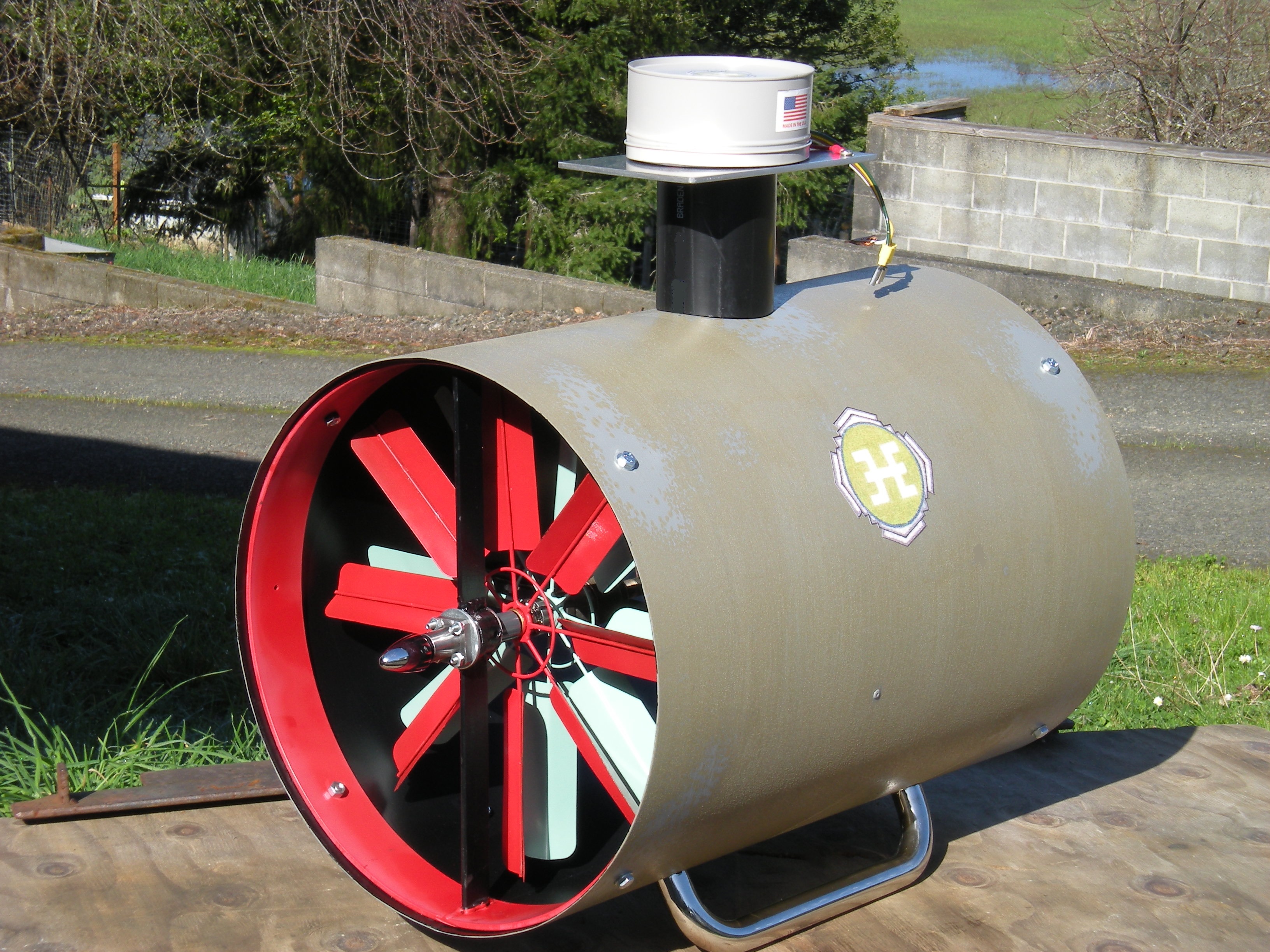
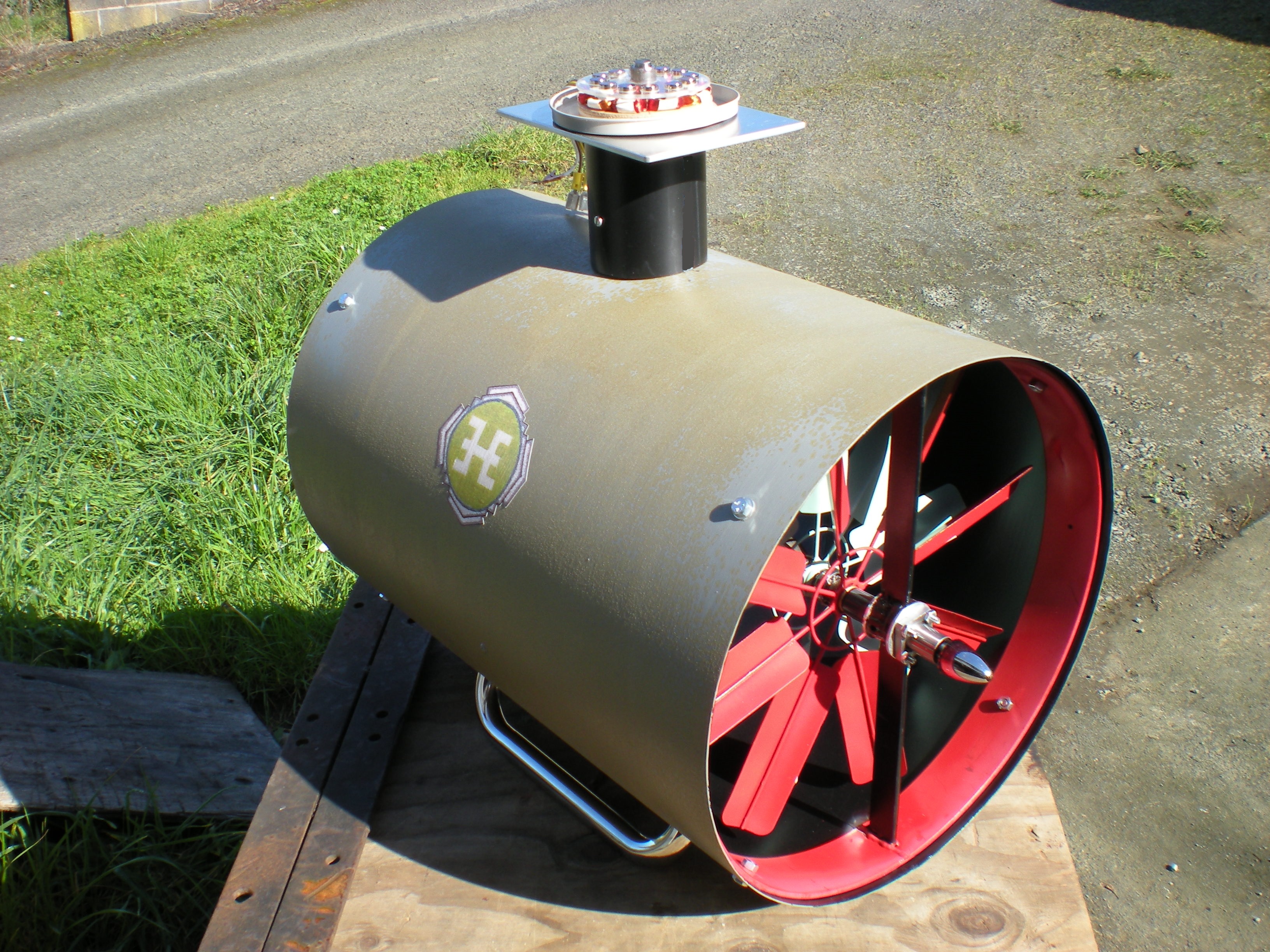
The completed proof-of-concept demonstration model as it would appear in the OWC air turbine application. In the cross-current tidal application, it will have fewer impeller blades and will spin slower due to the higher density of water. No fish will be harmed.
________________________________________________________________________________________________________________________________________________________
Inventor: John Clark Hanna
Provisional patent: 62/708,462 (expired)
Title of the Invention
"Hanna Monoradial Closed Loop Drive"
The Hanna Monoradial Drive was the subject of a U.S. Department of Energy numerical and CFD study in 2022. The study's report can be read in the "FEATURED" section of the inventor's LinkedIn page. Go to: https://www.linkedin.com/in/john-clark-hanna-89024943/
ABSTRACT:
Described herein is a pneumatic primary drive that is activated by the up and down movement of oceanic waves. The cyclic motion of waves is converted into a bi-directional air flow developed by either the Oscillating Water Column (OWC) or Oscillating Air Column (OAC) principles. Both systems will create a reciprocating air flow. This reversing air stream is then mechanically converted by the present invention to produce a one way rotational force upon a single radial-vane rotor which, in turn, spins a generator. The invention can be scaled. Smaller versions can produce low-wattage power to maintain a charge for batteries in research and data acquisition buoys. Large versions can be utilized for utility grade shore based power plants or as PTO’s for surface or submerged wave energy converters.
OPERATING PRINCIPLE:
Generally, an OWC or OAC system is used to spin a self-rectifying turbine. Commonly these systems push air into a turbine as a wave crests. Because there is no suction on the downside of the turbine, the used air continues to be pushed out into the atmosphere. As the wave’s height falls off, air is drawn back through the turbine from the atmosphere. In most cases, an OWC is an open system. This is because it has an atmospheric component. Pushing air out of the system and into the atmosphere has a damping effect that reduces energy capture. Drawing air back in from the atmosphere is less dynamic (forceful) than the air that is pushed in from the ocean side. Thus, there are two inherent pressure losses at the turbine when air is either pushed in from the ocean side or when air reenters from the atmospheric side. The system is imbalanced.
The present invention is balanced. It has no atmospheric component. It is a closed loop system. The total movement of air is fully utilized within the rotor Casement (1). There are no pressure losses like those experienced in common OWC systems which have the atmospheric component in every half cycle. For the present invention, the pressure and velocity of air in both half cycles is virtually identical. Because of the closed loop configuration, there is a simultaneous push and pull of air. While one Nozzle (3) pushes air into the rotary drive, the opposing Nozzle (3) is sucking out air at the very same time.
The simultaneous push and pull alternates with each wave cycle. This arrangement produces less damping (resistance) and a more efficient power capture than seen with conventional OWC systems. The present invention uses two lightweight “Hinged Flappers” (4a and 4b) to redirect the alternating air flows within the sealed rotary drive. To produce angular momentum, one Flapper (4a) will direct air from a Nozzle (3a) onto the Rotor’s radial Collector Fins (2). Simultaneously, the other Flapper (4b) directs air to be sucked out at a second Nozzle (3b) which is placed on the opposite side of the rotary Casement (1). The position of either Flapper will simultaneously reverse at every half cycle of passing incident waves. The result is a Power Take-Off (PTO) that is mechanically rectified and maintains a continuous one way rotary force to efficiently spin a Generator (5).
DESCRIPTION of the INVENTION:
The PTO is a sealed, circular-shaped hollow Casement (1). The Casement contains a single light weight Rotor (2) with numerous slanted Collector Fins (2) placed around the Rotor’s periphery. The rotor’s spinning mass acts as a flywheel. There are two openings at opposite sides of the Casement. The openings serve as Nozzles (3a and 3b) to convey alternating streams of air. For instance, one Nozzle (3a) pushes air in while the opposite Nozzle (3b) is simultaneously sucking air out. Depending on which Nozzle has the incoming air, the relative position of either of the two Hinged Flappers (4a or 4b) will direct the incoming air flow to maintain a continuous one way movement of the Rotor (2). At the same instant, the outgoing air flow is being sucked out through the opposite Nozzle (3b). Then, when the air flow reverses direction, the V-shaped Hinged Flappers will instantaneously alternate their respective positions so the Rotor is able to spin continuously in the same direction.
The alternating air flows can be harvested by different types of OWC systems: by shore based installations; by submerged buoys and floating buoys. In each OWC system, the air flows move back and forth through the Monoradial Turbine. This bi-directional air flow can be developed by three methods: (1) The rise and fall of water in a typical jetty-based OWC capture chamber; (2) the rise and fall of the air/water interface within a submerged buoy and (3) by two opposing closed loop air bladders or bellows in moored or free-floating autonomous surface buoys. As one bladder expands, the other deflates. The Monoradial Turbine is placed between the two flexible bladders and the closed loop air flows spin a sealed generator. For details on how the Monoradial Turbine will power autonomous data collection buoys, click HERE.
BACKGROUND OF THE INVENTION:
The current invention is similar to the familiar water wheel which turns a shaft to do useful work, i.e. milling grain or corn. Another similar device is the Pelton Wheel, commonly used in hydropower plants to spin generators. Pelton wheels have peripheral buckets that fill with water, rotating the wheel and shaft. For wave energy conversion, there exists OWC-type, self-rectifying turbines of the Impulse or Reaction variety. As discussed in the previous Operating Principle section, these OWC-type turbines are open to the atmosphere and have uneven reciprocating flows caused by the less robust atmospheric half-cycle component.
An example of a patented PTO is a bi-radial turbine invented by Antonio Falcão and Luis Gato of Portugal (US 9,371,815 B2). This device has two radial rotors and is energized by an open OWC air flow. It is not a closed loop design.
Additional examples of prior art are: M3 Wave’s subsurface device that uses closed loop differential pressures and dual flexible air bladders to drive a turbine, WO 2013/019214 A1; a subsurface closed loop buoy that uses a turbine by S.K. Song, US 9,518,556 B2; a submerged device by 40South Energy, CA 2,670,311 C, and an invention by W.W. Hirsch, US 7,199,481 B2.
CONCLUSION:
The present invention is an improved PTO. Since it is a closed loop system, the inefficient losses seen in open systems are eliminated. These inefficiencies are caused by damped air flows being pushed in from the ocean side and weaker flows being drawn back in from the atmosphere. The present design is not a turbine. It is more accurately a simple air wheel that is rotated by alternating air flows within a closed loop system. The closed loop design spins a generator with greater efficiency than prior art designs which use an open-ended OWC system. Reciprocating air flows coming in and exiting the sealed Casement are always equal. The simultaneous “push and pull” of the air streams reduce drag and resistance so more energy is conserved to spin the rotor. The new design is simple to manufacture with only one moving part. No components come in contact with water. The use of two Hinged Flappers is a novel, uncomplicated means of mechanically rectifying the bi-directional air flows to continuously spin the rotor in one direction only. The device will not contaminate the ocean. The primary driving force is clean pneumatic energy.
The Hanna Monoradial Turbine design can also be used in conventional OWC open-ended systems. The open-ended design uses solenoids to activate the V-shaped Hinged Flapper guides. The open-ended turbine can be installed on either shore-based jetties or surface buoys to generate utility grade power. In some instances, the open-ended monoradial turbine can use the “Air Entrainment Principle” during the atmospheric intake half-cycle. This will greatly improve performance of the open-ended OWC iteration.
NOMENCLATURE of the TWO FIGURES:
1: Sealed Casement 4: Hinged Flappers (a) and (b)
2: Rotor with Collector Fins 5: Generator Housing
3: Inlet and Outlet Nozzles (a) and (b)


Closed loop configuration
Open-ended configuration
Turbo-Gen with axial flux generator